Steel as a Lighting Substrate: Fixing Pendants and Linear Runs to Exposed Beams in Loft Conversions
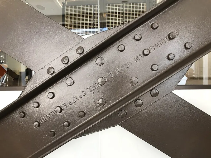
Photo: Kgbo, CC BY-SA 4.0, via Wikimedia Commons
The moment a loft conversion exposes its steel, the structure becomes the ceiling. Purlins, universal beams and columns stop being hidden infrastructure and start doing visual work, which means every luminaire fixed to them is on show at close range and at an awkward angle. In practice, lighting is the last trade to be consulted and the first to be compromised. The result is familiar: a run of pendants bolted to a bottom flange with no relationship to the beam grid, a cable stapled down a web, and a downlight cutting through a fire-rated membrane directly above a steel member.
The remedy is procedural rather than decorative. Decide the fixing family before the fittings are ordered, and the detail will look deliberate.
Read the beam schedule before the lighting layout
A domestic loft rarely contains more than a handful of member types, but the differences matter. A 152 x 89 universal beam presents a narrow bottom flange and little room for a clamp jaw; a 203 x 133 offers a working surface of roughly 130 mm across the flange, which will comfortably take a clamp body and a cable drop. Columns are usually 152 x 152 UC, whose flat faces accept surface-mounted boxes more readily than curved or castellated profiles.
Three pieces of information should be extracted from the engineer's drawings at the outset: the flange width and thickness of every member receiving a fitting, the fire protection specification, and the position of connections and stiffeners. Thin-film intumescent coatings are particularly relevant, because any clamp that bites into the coating creates a local repair obligation and, in many cases, requires the coating manufacturer's written acceptance. Boarded protection is more forgiving but removes the magnetic option entirely.
Three fixing families and where each belongs
Beam clamps. A jaw clamp on the bottom flange is the most economical and most reversible solution for individual pendants and small wall-mounted arms. Specify a clamp rated meaningfully above the fitting weight, allow for the cable gland, and check that the jaw will not foul the web fillet. Clamps suit loads of a few kilograms and should not be used to support long linear assemblies without intermediate support.
Magnetic track. Where bare, ferromagnetic steel is exposed and the coating system permits, low-voltage magnetic track clipped to the underside of a flange gives remarkable flexibility, allowing fittings to be repositioned after handover. Two caveats apply: magnetic track is not a structural fixing, so it must be independently supported; and the track and its drivers must be kept clear of any surface likely to exceed the manufacturer's temperature limit.
Fabricated brackets. Where the design intent is a continuous line of light parallel to a beam, a purpose-made bracket is usually the cleanest answer. A folded mild steel section, powder coated to match the beam, gripping the web rather than the flange edge, gives a stable and repeatable datum. Specify galvanised or zinc-rich primed steel where the loft is cold, ventilated and prone to condensation, and design the bracket so that fixing holes fall outside the connection zones.
Cable routes that read as intention
Visible wiring on exposed steel is either a design feature or an error, and the difference is consistency. Two approaches work. The first is to accept the cable and give it a route: 20 mm black enamelled conduit clipped along the web, dropping through a grommeted hole in the flange to the fitting. The second is to conceal it entirely, running cabling above the insulation line and emerging only at the point of use.
Drilling steel is where projects come unstuck. Holes in webs should be referred to the structural engineer and kept well away from connections, stiffeners and mid-span bending zones; holes in flanges, particularly tension flanges, are generally not acceptable without explicit approval. Cable derating also needs thought: a cable clipped to a steel member that will sit against a warm ceiling build-up is not in free air, and grouping several circuits on one run compounds the correction factors.
The ceiling line and fire resistance
Where a new floor separates the loft from the rooms below, the ceiling beneath is usually a rated element, commonly thirty or sixty minutes. Recessed downlights compromise that membrane unless they are fire-rated assemblies installed to the manufacturer's tested detail. On a steel-framed loft there is rarely a good reason to cut the ceiling at all: surface-mounted cylinders, track and linear sections can all be fixed to the structure above, leaving the membrane intact. Where a cable must pass through, specify an intumescent grommet or seal rather than a bead of mastic.
Who signs off what
The structural engineer confirms the fixing positions, permitted holes and any bracket loading. The building control body is concerned with Part B for the fire performance of the floor and any new escape routes, and with Part L for lighting efficacy. The electrician certifies the installation to BS 7671 and, in England and Wales, notifies new circuits under Part P. Listed building consent and conservation area considerations rarely apply to loft steel itself, but they frequently apply to what is visible through a roof light.
A coordination sequence that holds
- Obtain the beam schedule and fire protection specification.
- Set the lighting layout against the beam grid, not the room grid.
- Choose the fixing family for each member and confirm it with the engineer.
- Agree cable routes and any penetrations before the ceiling is boarded.
- Install a single mock-up bay for client sign-off.
- Record the as-fitted positions for the operation and maintenance file.
Handled in that order, exposed steel stops being an obstruction and starts behaving as a lighting substrate, which is what it is.